The 2022 California Building Code (Title 24, Part 2), based on IBC 2021, mandates thorough subsurface characterization before structural design in Roseville. Surface clays overlying deeply weathered granitic bedrock — typical of the Penryn-Roseville corridor — create sharp resistivity contrasts that conventional borings often miss between grid points. Electrical resistivity tomography and vertical electrical sounding resolve these transitions without disturbing the ground, delivering continuous profiles across sites where the shallow water table fluctuates seasonally with Dry Creek and Cirby Creek. For projects near the active Foothill fault system, we integrate the geoelectric data with CPT testing to verify soft zones, and with MASW surveys to correlate resistivity with shear-wave velocity across the Placer County substrate.
Resistivity profiling maps the granite weathering front continuously, revealing depth-to-bedrock variations that isolated boreholes miss.
Our approach and scope
Local ground factors
Roseville's expansion from a small railroad town in the 1860s into Placer County's largest city has pushed development onto residual granite soils that weather unevenly. Corestones — rounded, unweathered granite boulders — float within completely decomposed saprolite, creating a heterogeneous subsurface where foundation loads concentrate unpredictably. Missed corestones cause differential settlement in shallow footings, while undetected clay-filled troughs in the bedrock surface trap groundwater and delay excavation dewatering. Resistivity methods identify these features before grading begins because the intact granite cores show resistivity above 400 ohm-m, whereas the surrounding clayey saprolite reads below 30 ohm-m. The sharp electrical contrast makes VES a practical reconnaissance tool for shallow foundation design and for siting stormwater infiltration basins where the IBC requires knowing the seasonal high groundwater elevation.
Applicable standards
ASTM D6431-18 Standard Guide for Using the Direct Current Resistivity Method for Subsurface Site Characterization, 2022 California Building Code (Title 24, Part 2), Chapter 18 Soils and Foundations, ASCE 7-22 Minimum Design Loads and Associated Criteria for Buildings and Other Structures
Complementary services
2D Electrical Resistivity Tomography
Continuous cross-sections along survey lines up to 300 meters. We map the granite weathering profile, locate paleochannels, and delineate the saturated zone — essential data for cut-and-fill earthwork estimates.
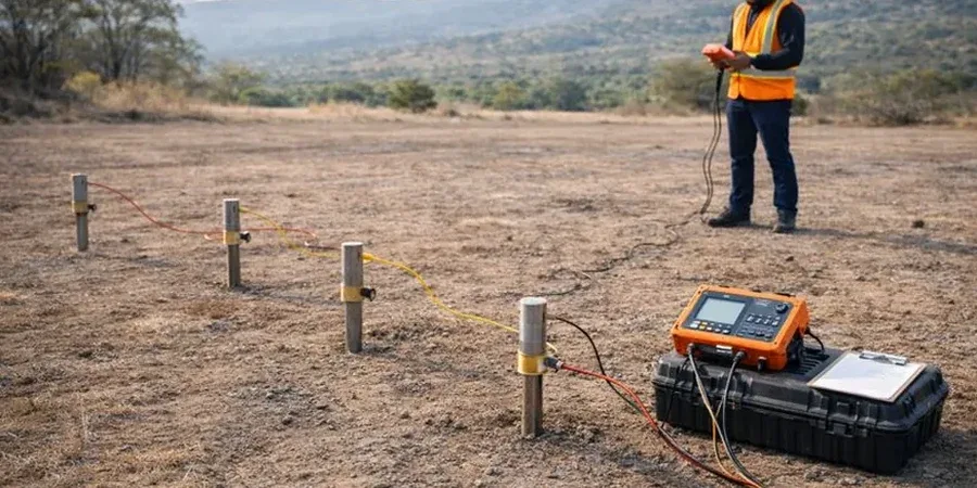
Vertical Electrical Sounding (VES)
Single-point depth soundings using the Schlumberger array. Efficient for estimating bedrock depth across large parcels before laying out detailed boring plans, calibrated with nearby CPT or SPT data.
Typical parameters
Quick answers
What depth can electrical resistivity reach in Roseville soils?
With a 235-meter maximum electrode spread using the Schlumberger array, VES typically reaches 40 to 50 meters in the decomposed granite and clay soils common around Roseville. The actual penetration depends on the near-surface resistivity — conductive clays limit depth more than dry sandy layers do. We adjust the spread length on site based on initial readings.
How much does a resistivity survey cost for a typical residential lot?
A resistivity survey for a standard residential parcel in Roseville generally ranges from US$600 to US$1,170. The final cost depends on the number of survey lines, electrode spacing, and whether we include topographic correction. Commercial sites requiring multiple cross-lines and deeper penetration fall toward the upper end of that range.
Can resistivity distinguish between wet clay and decomposed granite?
Yes, and the contrast is usually clear. Saturated clay in the Roseville area commonly reads 10 to 30 ohm-m, while decomposed granite even when moist stays above 80 ohm-m. Fresh granite exceeds 400 ohm-m. We calibrate these values against at least one borehole or test pit on site to confirm the interpretation.
Does cultural noise from Roseville utilities affect the data?
Power lines, buried pipes, and reinforced concrete can introduce noise. Our acquisition system uses automatic stacking and notch filters at 60 Hz to suppress interference. We also orient survey lines perpendicular to known utilities where possible, and note any residual noise in the final report so the geotechnical engineer can account for it.
What deliverables do I receive from a VES survey?
You receive a report containing apparent resistivity curves, the inverted 1D resistivity model with layer thicknesses and resistivities, a depth-to-bedrock estimate, and correlation notes if borehole data was available. For 2D tomography, we include color-contoured cross-sections with lithologic interpretations overlaid.